Simulation-based system tests –
a key to the digitalization of the rail system
Digitale Schiene Deutschlands projects, such as driverless, fully automated driving (Automatic Train Operation in Grade of Automation 4 / ATO GoA 4), must be extensively verified, validated and tested. Simulation-based system tests are a key element in overcoming this challenge.
Requirements for a simulation environment for fully automated rail vehicles
Due to limited resources, such as the availability and number of test tracks and the high safety standards to be met, testing under real conditions is very complex, time-consuming and costly. For these reasons, the aim is to carry out as many development, verification and validation processes as possible in a simulated environment.
Test projects for driverless driving at automation level GoA4 are particularly complex. A variety of scenarios must be considered and tested. To ensure that this can be implemented in a realistic timeframe for an ATO GoA4 project, a rail vehicle must be simulated in its operating environment. The simulation and the tools used for it must be qualified for testing safety-critical functions. In future, this will allow as many tests as possible to be transferred from the field to the laboratory.
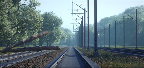
An ATO GoA4 system in a rail vehicle takes over all the actions of the train driver. This essentially includes starting up and shutting down the traction unit. Also monitoring changes of passengers and driving, including route monitoring during the journey. It must also be able to react to extraordinary situations, such as unexpected objects in the track area (e.g. trees, people, animals), critical weather conditions (e.g. flooding of the tracks) and dangerous incidents on the train (e.g. fire).
The main subsystems of such a fully automated ATO GoA4 system are the ATO Onboard, i.e. the automation of the actual driving function (starting, accelerating, braking, stopping) and the Perception System (PER). The latter is based on data from complex sensor systems consisting of cameras, radars and LiDARs. Another subsystem is the Incident Prevention Management System (IPM), which assesses whether a regular or irregular situation exists based on the objects detected by the perception system and triggers a response if necessary.
These subsystems are usually connected to the central control of the rail vehicle , also known as the Train Control Management System (TCMS), the onboard Train Control System (CCS) and other systems and interact with the Physical Train Unit (PTU), see Figure 1.
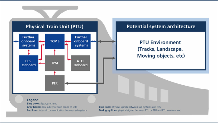
To investigate how a simulation environment for testing GoA4 systems can be implemented, a cooperation was set up with dSPACE GmbH, which has more than 30 years of experience in this field. The first step was to carry out a proof of concept. The focus here was on testing the new IPM subsystem. Deutsche Bahn provided a simplified IPM model for the proof of concept, which was embedded in a closed loop into the dSPACE simulation environment. For this purpose, all other required subsystems such as the perception system and other connected onboard systems (e.g. brake/drive/CCS onboard) as well as the train dynamics and the train environment (PTU) must be simulated.
Creating the simulation environment
First, a simulation model was needed that provides a suitable representation of the train dynamics and takes into account the structure of different train formations. The aim was to implement a generic train dynamics model that initially focuses on longitudinal dynamics. The dSPACE product "Automotive Simulation Models" (ASM) was used for this purpose. Railway-specific model adaptations were made to the ASM vehicle dynamics model from dSPACE.
The vehicle dynamics model was parameterized using ModelDesk, another dSPACE product. For the proof of concept, it was parameterized in such a way that it corresponds to a series 423 of Deutsche Bahn AG with four cars.
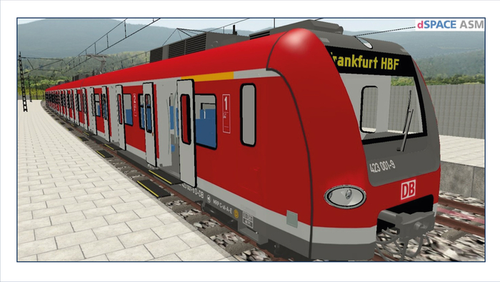
By importing railway-specific objects such as rails, catenary masts and light signals, the basic road visualization was replaced with a railway-like environment. For demonstration purposes, a railroad track network from OpenStreetMap was also imported into ModelDesk. However, since the dSPACE conversion tool is designed for importing road networks and their objects, some rail-specific elements such as rails, overhead lines and platforms had to be added manually. The plan is for this data to be imported from the Digital Register, a "single source of truth" for infrastructure data, which is also being developed by Digitale Schiene Deutschland. MotionDesk was initially used for the visualization (see Figure 2).
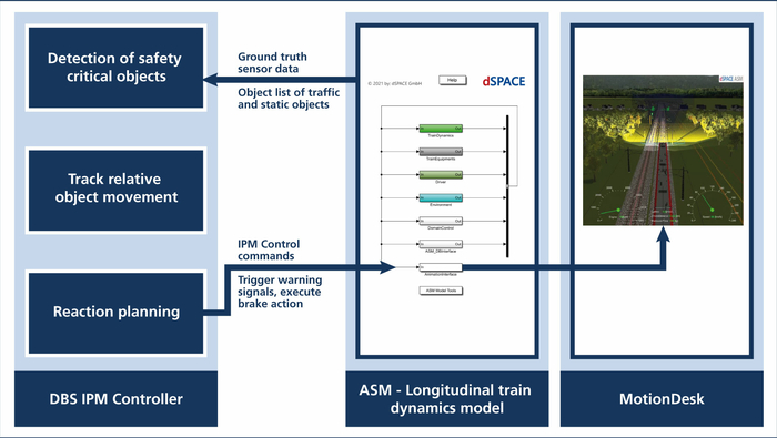
The next step was to integrate a simplified IPM controller provided by Deutsche Bahn to form a closed control loop with the ASM model. The IPM controller receives its input from a simulated perception system. To simplify matters, the object lists provided by the ASM Ground Truth sensor models were used for this purpose. Based on the detected objects, the IPM controller determines whether the train must react to the objects. The desired reaction, such as the triggering of warning signals, the initiation of a regular or emergency braking, was transmitted back to the ASM train dynamics model, which executed this reaction. A schematic representation of the control loop is shown in Figure 3.
Evaluation of the simulation
In order to test the suitability of the simulation environment created and the associated dSPACE tool chain for Digitale Schiene Deutschland, two different use cases were created:
The first use case involves a situation in which a deer crosses the tracks. Using the 3D Ground truth sensors the deer is identified as a moving object of the type “animal”. This information is then transferred to the IPM controller. IPM reacts to the object on the tracks by activating the horn, a visual warning signal and the emergency brake (EB). If the deer leaves the track area and is no longer detected, the train resumes normal operation. The second successfully developed use case involves the following situation: A train is approaching a level crossing. A car is parked on the tracks. This scenario is shown in Figure 4.
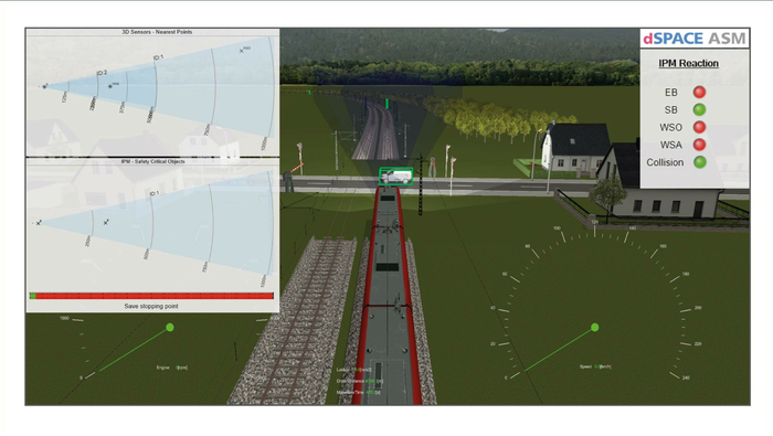
As shown in the figure above in the upper left corner several objects are detected when approaching the level crossing. Only two objects appear to be in the path of the train (which is in the figure above indicated with the green rectangles) and are classified as safety-critical by the IPM controller (figure on the left in the middle). The reaction to this is a visual warning via headlights and a horn warning with service brake (SB). If it is no longer possible to stop with the service brake due to the insufficient distance to the vehicle, the emergency brake (EB) is activated by the IPM controller. Due to the reduced remaining safe stopping distance, the IPM controller triggers the emergency brake (EB), the visual warning signal (WSO) and the audible warning signal (WSA) (see also the table at the top right of Figure 4). In this case, the train can brake just in time.
These two simulated use cases provided important insights into sensor positioning and object detection. The environment perception sensors create object lists with all objects in their cone-shaped observation area, which are passed on to the IPM model. However, if a safety-critical object disappeared from the observation area (the cone) of the sensors, although it is still in the danger zone, the IPM model returned to normal operation in the simulation. In this case an undesired outcome. As a consequence, both the sensor positioning (for better permanent coverage) and the overly simple control strategy, which did not include the observation history, had to be reconsidered and improved. This example shows that simulation can make a significant contribution to validating the system or controller design at an early stage and thus keeping the costs of error correction low.
Challenges and outlook
The proof of concept shows that it is possible to adapt the dSPACE tool chain from the automotive environment and build a simulation environment that is suitable for future system tests. As the proof of concept met the expectations of both parties, DB InfraGO AG and dSPACE are planning to intensify their cooperation by jointly expanding the implemented railroad simulation environment.
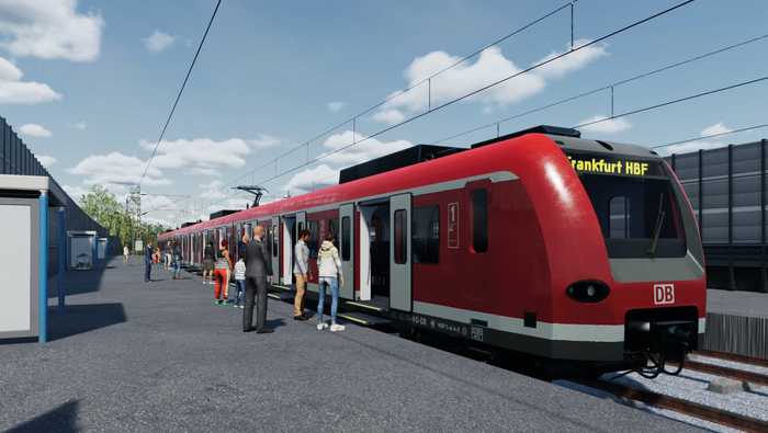
Among other things, MotionDesk has already been replaced by the new AURELION tool. The first results of the migration are shown in Figure 5. AURELION enables a more realistic environment visualization and a physically realistic sensor simulation for camera, Lidar and RADAR sensors. This will be necessary if the perception system also becomes part of the system to be tested in the lab. Sensor effects such as deflection and multipath propagation for radar sensors or point cloud distributions and motion distortion effects for Lidar sensors would then have to be taken into account.
The next major step planned is to use the simulation environment for software and hardware tests in the Automated Train project launched this year.
Authors:
Dr. Dirk Spenneberg, DB InfraGO AG
Niklas Kersting, dSPACEGmbH
Roa Al-Hashimi, DB InfraGO AG
A detailed report was published in the magazine „Deine Bahn“ (11/2023)
